
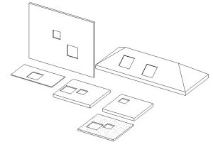
In this Click Savers I want to discuss a family that is missing from the Revit platform. I get asked quite a lot about doing depressions in slabs, floors, and walls with Revit. Out of the box there is not a simple family to do this but let’s learn how to build one.

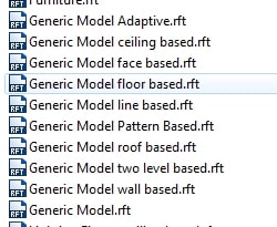
We will start with an out of the box family template but you will need to decide which face based family you would want to use. Notice in the below list that there a few to choose from that have a suffix of “Based” in the name. So depending on the type of depression that you are wanting to do on a particular modeling element depends on which one to start with. There is one family called Generic Model face based that will go onto any surface that you choose.
![]()
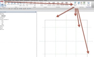
For today to cover the bases I will start with the Generic Model face based.rft template. The goal is being able to put this on any surface and to control the width, length, and depth. The first thing is building four additional reference planes to control the length and width.
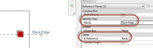
I like to pick on the reference planes and in the properties give each reference plane a name and also change the “Is Reference” from Weak Reference to Front, Back, Right, and Left to each appropriate reference plane. This way I can dimension to the edges of the depression if I need to.
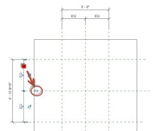
Now we need to add the dimensions for the overall width, length, and equal the edges around the center two reference planes.
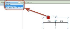
Now select one of the dimensions and on the Option Bar choose Label. On the drop-down choose Add Parameter.
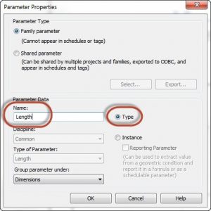
This will now open the parameter properties dialog box. Since I choose the horizontal dimension I’m going to name it Length and keep it as a Type parameter and pick Ok. Do this again for the vertical dimension and call it Width and keep it as a Type parameter.
We need to see if the reference planes are flexing correctly. Select on the Family Types tool and change the numbers for Width and Length and pick on Apply.
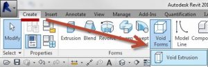
Now we are going to create the Void that will cut the model objects in our project. Go to the Create tab and choose Void Forms, on the drop-down pick on Void Extrusion.
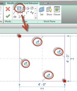
Using the Draw panel choose Rectangle and select the two corners of the reference planes. By using the rectangle command it will automatically show you the Locks to lock the lines to the reference planes. Pick on each lock to lock it, if for some reason you miss this step you will need to use the Align tool and select the reference plane and then the line and lock each one.
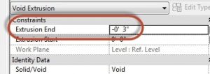
In the Properties change the Extrusion End to smaller number like -3”. Now choose the Green Check Mark on the Ribbon to close the void tool.
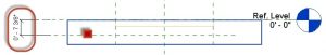
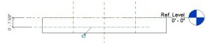
Now we need to change to a front view using the Project Browser so we can control the depth of the depression. In the front view start the reference Plane tool again and draw a reference plane under the orange box which is your void and draw an Aligned dimension from the Ref. Level to the reference plane.
Now use the Align tool and select the reference plane first and then the bottom of the void. Use the Lock to lock them together.
Pick on the vertical dimension and on the Options Bar choose Label. Add another parameter and call it Depth and keep it as a Type.
One last step to do, on the Project Browser get into the default 3D view. We need to tell Revit that the void cuts the model element that is the family, this way as we add it to our project it knows to cut whatever object that we put it on. Go to the Modify tab and choose Cut from the Geometry panel. Choose the edge of the model element first and then the edge of the void. It should now truly look like it is a depression in the modeling element.
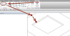
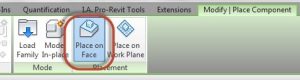
Name you family and place it in your favorite folder and load it into your project. Use the Component tool to place on any modeling object, remember to look at the Ribbon for the option to Place on Face.
That was a few steps to do but now you have a depression family that you can use any time you want in Revit. See you in class or at your office, Jarod

